Gym-induced vibration problem
To facilitate the rapid conversion of a suspended office floor to an office gym in a city centre mul ...
Read
MoreA new long-span steel–concrete composite office floor, with unusually large 16 m × 12 m open-plan bays, exhibited vibration issues under normal walking conditions. Three floor bays, totalling approximately 500 m², were identified as requiring vibration control.
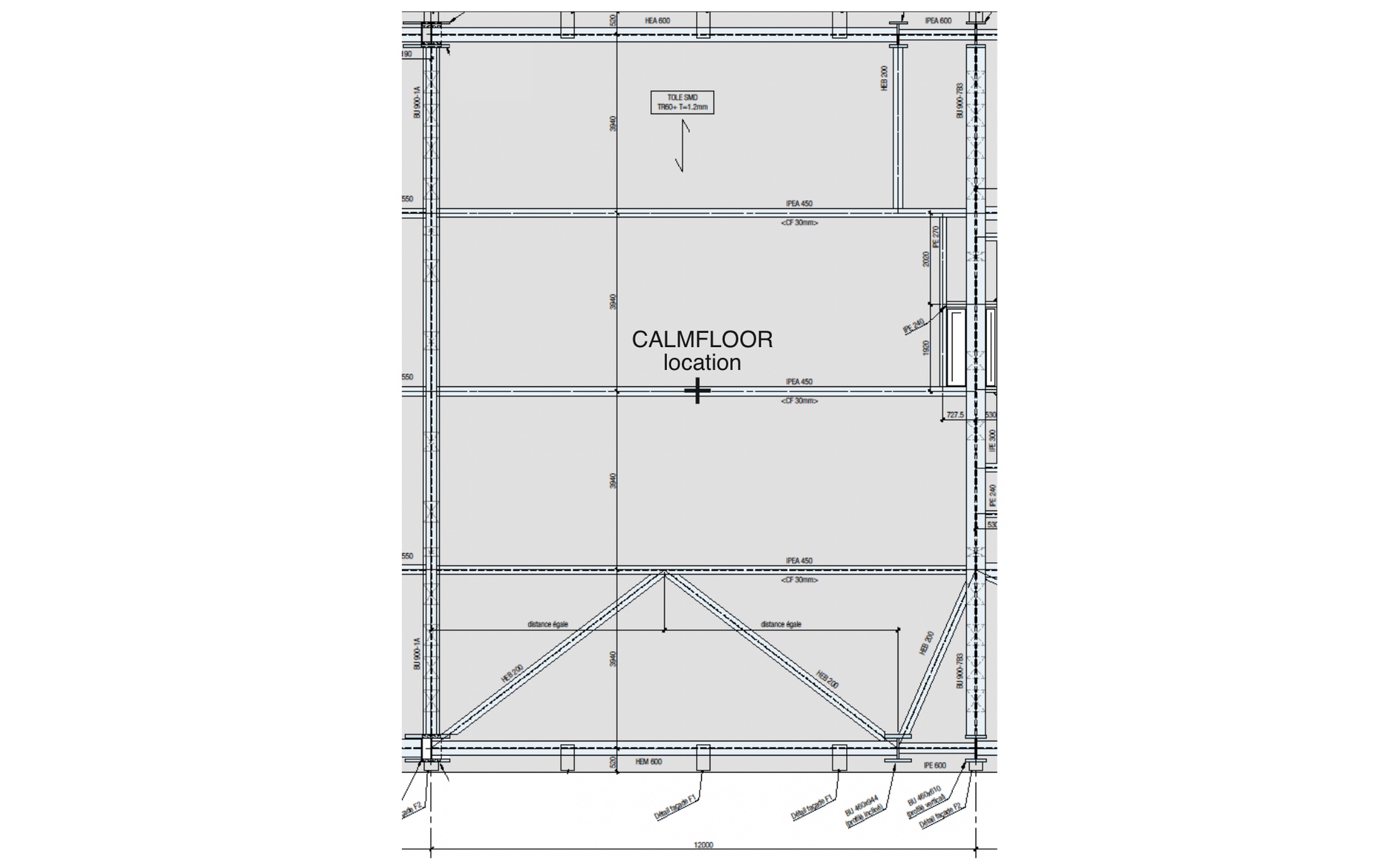
Primary I-beams, approximately 1000 mm deep, span 16 m and support 450 mm deep secondary I-beams spanning 12 m, and framing into the primary beams at 4 m centres. This structural arrangement is complemented by a 140 mm concrete slab acting compositely with the steel beams below.
The floor has multiple closely spaced modes of vibration, which are low frequency and typical for this type of long-span, open-plan structure with repetitive geometry. The dominant natural frequencies for individual bays are around 5.0 Hz. This coincidies with the so called ‘third harmonic’ of the vertical dynamic force caused by walking at 1.6–1.7 steps per second, a common pacing frequency in offices.
As a result, normal circulation of office users regularly caused bursts of near-resonant vertical floor vibrations, noticeable to and affecting occupants who were stationary and seated.
Independent measurements showed vibration levels approximately twice the acceptable limits proposed by American National Standards Institute (ANSI) and the International Organization for Standardization (ISO). This explains why the floor was perceived as too ‘lively’ during normal day-to-day use: it regularly experienced clearly perceptible vertical vibrations.

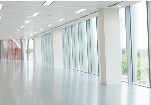
The building is an architectural landmark with high-spec open-plan offices, making structural modification impractical and undesirable.
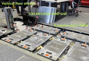
Initial mitigation employed six low-profile tuned mass dampers (TMDs), which achieved only limited improvement. CALMFLOOR was subsequently trialled on site, offering a practical and readily demonstrable alternative solution. This also provided, for the first time, an opportunity to carry out a direct in-situ comparison between the floor vibration reduction performance achieved by six TMDs operating in unison and a single CALMFLOOR active mass damper (AMD).
The trial was supported by an independent vibration measurement consultant. Using their own accelerometers and a vertical shaker, the consultant measured the floor frequency response functions (FRFs) both with and without the TMDs and AMD operating. Measurement of FRFs is a widely used and effective method for comparing the performance of floor vibration control solutions.
The plot below shows the so-called ‘point accelerance FRF’ corresponding to the vertical excitation and response measured at the test location.
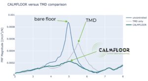
The solid blue line shows the FRF modulus of the uncontrolled floor, with the masses of the six TMDs locked and not moving and the CALMFLOOR AMD switched off. This plot clearly shows a strong vertical vibration mode at around 5 Hz that required control, as previously mentioned.
The solid grey line shows the FRF modulus measured with the TMDs unlocked and their masses moving, while CALMFLOOR was switched off. This shows the TMDs reduced the vibration by producing classical mode splitting: one mode at about 3.8 Hz and one at about 5.6 Hz. However, this is not the neat symmetric split expected from a well-tuned passive mass damper. The two peaks are asymmetric, with the peak around 5.6 Hz significantly higher, resulting in a vibration reduction of the FRF peak of approximately 40%.
This is a common problem in lightweight floor structures in office buildings, where floor utilisation can change frequently. Such changes may include the location and type of non-structural partitions and furniture. These modifications can significantly alter the stiffness and mass distribution (i.e. the modal properties) of the floor used for the initial TMD tuning, leading to detuning and reduced performance of the previously installed TMDs.
As a result, the significant moving mass of the six TMDs, totalling 1,500 kg, achieved only a 40% reduction of the FRF peak. The perceptible floor vibration was still easy to excite by normal walking. This was despite over 15 kN of static weight from the TMDs applied over a relatively small area of the floor. This concentrated weight presents a significant structural challenge: it reduces the floor’s capacity to carry useful live loading for which it was originally designed.
The thick green line shows the FRF modulus with the TMDs locked and only the AMD operating. The shape of the FRF modulus shows that a single CALMFLOOR unit significantly increased damping and reduced the FRF peak by 75%. The 35 kg moving mass of the AMD outperformed the 1,500 kg TMD counterpart. A single CALMFLOOR unit was demonstrably able to control a broad range of frequencies between approx. 3.5 Hz and 6 Hz.
This exercise demonstrates two groups of key advantages of CALMFLOOR AMD compared with passive TMDs when controlling floor vibrations:
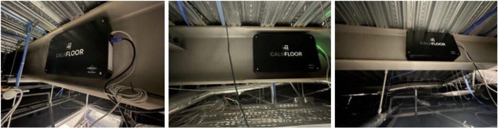
Having established the potential for excellent in-situ performance of CALMFLOOR, a total of three units were installed and commissioned. One unit per floor bay were used, with three units controlling a total area of approximately 500 m². The three CALMFLOOR units were attached to the webs of the secondary I-beams located close to the centre of each bay.
The figure below shows the three installed CALMFLOOR units. All units were installed in just 4 hours by two technicians using a mobile elevated platform. The installers had not previously worked with CALMFLOOR units and simply followed the published installation guidance.
Performance evaluation was carried out by an independent consultant. The CALMFLOOR units were switched on and off during different working days over a period of several weeks. Floor vibration was measured over 12 hours, between 7 am and 7 pm, during both CALMFLOOR ‘on’ and ‘off’ days. These days were, naturally, different, but selected to be nominally identical in terms of floor utilisation, allowing a like-for-like comparison.
The measured vertical floor vibration levels were expressed in terms of frequency-weighted R factors, calculated every 1 s over the 12-hour daily monitoring period. R = 1 corresponds with baseline acceleration of 0.005 m/s² RMS and the R factor value at any time indicates the multiple of this baseline that is being experienced by occupants.
The data are shown in the plots below – one for each of the installed CALMFLOOR units shown. The vertical axis shows the number of seconds the floor vibration is greater than the R factor shown on the horizontal axis.
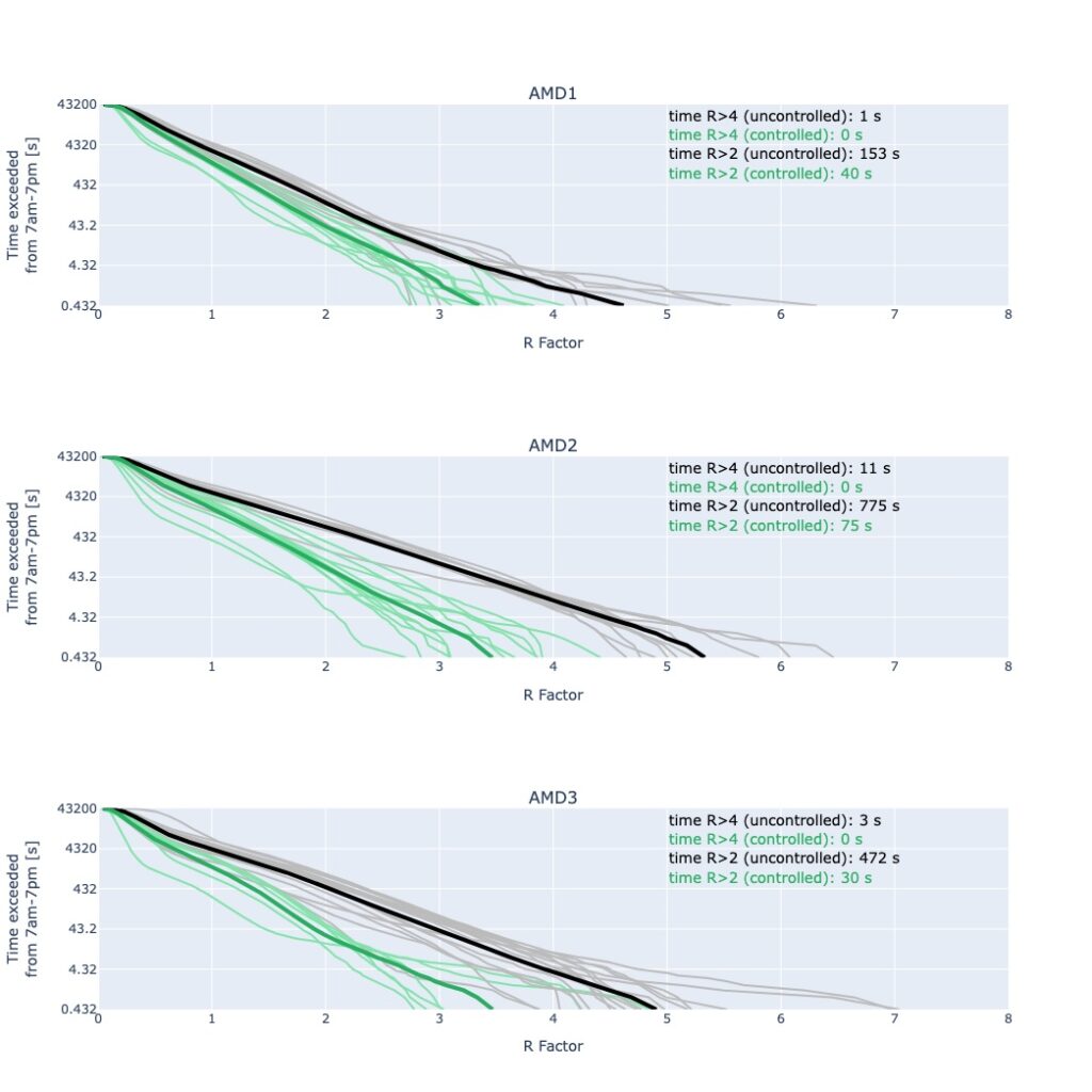
The thick black line shows the average performance when CALMFLOOR was switched off, and the thick green line shows the average when CALMFLOOR was running.
Floor vibrations above R = 2 are considered perceptible. CALMFLOOR significantly reduced the duration when floor vibrations were higher.
For example, at the location of middle unit (AMD2), the duration of R > 2 was reduced from 775 s per 12h to only 75 s, perceived by users as a considerable improvement.
R < 2 is not a formal vibration criterion for offices. However, a significant number of vibration events in the range of 2 > R > 4 can result in complaints, despite being technically acceptable.
Indeed, the baseline plots show that R = 4 was exceeded only rarely and R = 7 (approximately corresponding to the 0.5%g limit often used in the USA) was never reached at all. Yet the actual floor vibration performance was still considered by users to be unsatisfactory. Hence, frequent occurrences of just perceptible, rather than excessive, vibrations may drive adverse user perception.
Regardless of the criterion considered, CALMFLOOR considerably reduced the duration of exceedance across all R factors. The office criterion R > 4 was never reached at all three locations when CALMFLOOR was operating.
The adverse vibration conditions on this floor were known to be related to human walking excitation. However, the number and location of occupants contributing to the perceived vibration remained unknown. These are key uncertainties in current floor vibration design.
This case therefore demonstrates that CALMFLOOR is also an effective risk management tool, capable of reducing the duration of exceedance of vibration levels across the floor plate over a broad range of likely excitation conditions, even when these are not precisely known.
Most importantly, the floor users judged the vibration performance with CALMFLOOR to be satisfactory, with the original floor vibration serviceability problem considered resolved.
… the floor users judged the vibration performance with CALMFLOOR to be satisfactory, with the original floor vibration serviceability problem considered resolved.